Writing a simple VM in less than 125 lines of C
This tutorial is intended for intermediate C developers who want to get some coding practice and, in the process, gain valuable insights into low-level programming and how (some) Virtual Machines operate under the hood.
The reader should already be comfortable with bitwise operations, hexadecimal notation, pointers, function pointers, C macros, and basic standard library functions (e.g., fwrite and fread).
Note: If you are not familiar with bitwise operations, you can follow my tutorial here.
By the end of this article, we will have a working register-based VM capable of interpreting and running a limited set of ASM instructions, along with some bonus programs to test if everything works well.
The code is written in standard C11 and should compile cleanly on most operating systems. The repository can be found here, and the exact source code is in vm.c:
git clone git@github.com:nomemory/lc3-vm.git
It would be unfair not to mention some excellent existing blog posts covering the exact same topic; the absolute best in this category is Write your Own Virtual Machine by Justin Meiners and Ryan Pendleton. Their guide covers a much more in-depth implementation of a VM. Compared to their tutorial, our VM is a bit simpler, and the code takes a completely different route in terms of implementation.
After I published this article in December, Philip Chimento was kind enough to write a Rust implementation of the same Virtual Machine. If you are curious to see what the solution looks like in another programming language, please check it out here.
Virtual Machines
In the computing world, a VM (Virtual Machine) is a system that emulates or virtualizes a computer architecture or system.
Broadly speaking, there are two main categories of Virtual Machines:
- System Virtual Machines, which provide a complete substitute for a real machine. They implement enough functionality to allow full operating systems to run on them. They can share and manage hardware, meaning multiple environments can operate concurrently on the same physical machine without hindering each other.
- Process Virtual Machines, which are much simpler and are designed strictly to execute computer programs in a platform-agnostic environment. The JVM is a classic example of a Process Virtual Machine.
In this article, we will develop a basic Process Virtual Machine designed to execute simple programs in a platform-independent environment. Our toy Virtual Machine is based on the LC-3 Computer Architecture and will be capable of interpreting and executing a subset of LC-3 Assembly Code.
Little Computer 3, or LC-3, is a type of computer educational programming language, an assembly language, a type of low-level programming language. It features a relatively simple instruction set but can be used to write moderately complex assembly programs and is a viable target for a C compiler. The language is less complicated than x86 assembly but has many features similar to those in more complex languages. These features make it worthwhile for beginning instruction, so it is most often used to teach fundamentals of programming and computer architecture to computer science and computer engineering students. (Wikipedia)
For the sake of simplicity, we have deliberately stripped our LC-3 implementation of the following advanced features: interrupt processing, priority levels, process status registers (PSR), privilege modes, supervisor stack, and user stack. We will virtualize only the most basic hardware possible and interact with the outside world (stdin, stdout) purely through traps.
von Neumann model
Our LC-3 inspired VM, like most general-purpose computers today, is based on the von Neumann computer model. It will have three main components: the CPU, the Main Memory, and the Input/Output devices.
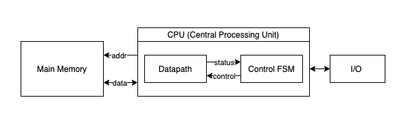
- The CPU, an abbreviation for Central Processing Unit, is the “circuitry” that controls and manipulates data. Furthermore, the CPU is divided into three primary sub-units: the ALU, the CU, and the Registers.
- The ALU stands for Arithmetic/Logic Unit and represents the circuits that actually carry out the instructions on the data (performing operations like ADD, XOR, DIV, etc.).
- The CU, an abbreviation for Control Unit, coordinates the activities within the CPU.
- The Registers are quickly accessible memory “slots” located directly at the CPU level. The ALU operates exclusively on registers. They come in small numbers (though this is a relative statement depending on the architecture), meaning the amount of data that can be loaded inside the CPU at any given moment is highly limited. We use registers to interact with the Main Memory. A typical scenario involves loading data from a memory location into a register, performing some operations on it, and then storing the result back into memory.
- The Main Memory can be imagined as an extensive “array” of
Wwords, with each word consisting ofNbits. Program instructions and their associated data are stored in the main memory in binary format. Each memory word contains either one single instruction or a piece of program data (e.g., a number used for computation). - The Input/Output devices enable the computer to communicate with the outside world.
Implementing the VM
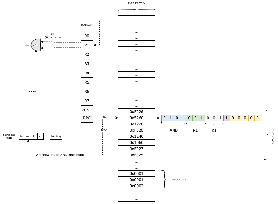
Our VM functions like this:
- We load the program into the main memory;
- In the
RPCregister, we keep the current instruction that we need to execute; - We obtain the Operation Code (first 4 bits) from the instruction and based on that, we decode the rest of the parameters.;
- We execute the method associated with the given instruction;
- We increment
RPCand we continue with the next instruction;
The Main Memory
Our virtual machine features a memory space consisting of W = UINT16_MAX words, each N = 16 bits wide. This memory structure is defined as a simple array:
uint16_t PC_START = 0x3000;
uint16_t mem[UINT16_MAX + 1] = {0};
The constant UINT16_MAX represents the maximum value of an unsigned 16-bit integer, which is 65535. By adding 1 to the array size, we create exactly 65,536 addressable slots (ranging from 0x0000 to 0xFFFF).
From a modern perspective, this system is quite constrained, because it cannot load programs exceeding 65,536 instructions or data words.
While this may seem restrictive today, it mirrors the humble hardware of several decades ago. Even with these limits, 65,535 words provide enough space to store several ASCII games and their associated data entirely in memory.
By convention, we begin loading programs at address 0x3000.
The memory region below 0x3000 is reserved for potential system components, such as a toy operating system or trap vectors. While building a full OS might be outside our current scope, maintaining this separation is a hallmark (fancy word!) of good architectural design.
To interact with the memory, we will use two helper functions for reading (mr) and writing (mw):
static inline uint16_t mr(uint16_t address) {
    return mem[address];
}

static inline void mw(uint16_t address, uint16_t val) {
    mem[address] = val;
}
While it might seem redundant to wrap a standard array access in functions, this abstraction is OKish. It isolates memory interaction, allowing us to easily add logic in the future.
The Registers
Our VM features a total of 10 registers, each 16 bits wide:
R0is a general-purpose register. It is also used for reading and writing data to and fromstdinandstdout.R1throughR7are additional general-purpose registers.RPC(Program Counter) is the register that holds the memory address of the next instruction to be executed.RCND(Condition Flag) is the conditional register. It stores status flags that provide information about the result of the most recent operation performed by the ALU (Arithmetic Logic Unit).
In C, we can implement the register set as an array and use an enum to define the indices for better readability:
enum regist { R0 = 0, R1, R2, R3, R4, R5, R6, R7, RPC, RCND, RCNT };
uint16_t reg[RCNT] = {0};
To access or modify a register, we simply use the array index: reg[R3] = ...;.
The Instructions
An instruction is essentially a command issued to the Virtual Machine.
Through these instructions, we direct the VM to perform specific, granular tasks: reading a character from the keyboard, adding two numbers, performing a bitwise AND on a register, and so on.
Instructions share the same word size as the memory: 16 bits. This is a logical design choice since instructions are stored directly within the Main Memory. Therefore, from a C perspective, instructions are represented as uint16_t unsigned integers.
Our VM supports a compact set of 16 instructions (technically 14, as two LC-3 instructions were redundant for this implementation).
Instruction Format and Decoding
Instructions are encoded into a uint16_t using the following format:
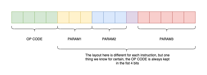
The first 4 bits always represent the OpCode (Operation Code). The remaining 12 bits encode 1, 2, or 3 parameters, depending on the specific instruction.
Once we identify the OpCode, we know exactly how to “decode” or extract the remaining parameters from the uint16_t. To extract the OpCode, we use a utility macro that employs a simple bitwise shift:
#define OPC(i) ((i)>>12)
By shifting 12 bits to the right (i >> 12), we isolate the 4 most significant bits:
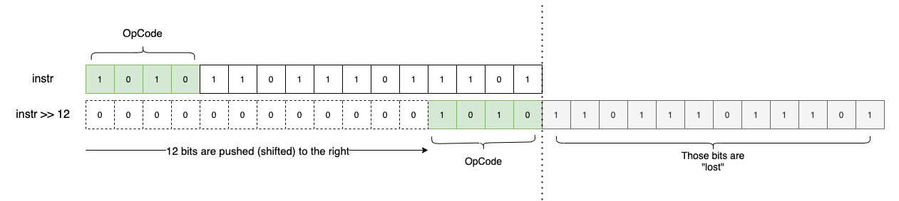
Since OpCodes are 4 bits wide, we can encode a maximum of 16 unique instructions ($2^4 = 16$).
A Clean Data Model in C
A powerful trick for organizing our VM is to store all possible instructions and their associated C functions in an array. The array index represents the OpCode (0 to 15), and the value is a pointer to the corresponding C function.
#define NOPS (16) // Total possible instructions
typedef void (*op_ex_f)(uint16_t instruction);

// ... implementation of instructions ...
static inline void add(uint16_t i)  { /* ... */ }
static inline void and(uint16_t i)  { /* ... */ }

// Function pointer array for instruction execution
op_ex_f op_ex[NOPS] = {
    br, add, ld, st, jsr, and, ldr, str, rti, not, ldi, sti, jmp, res, lea, trap
};
By using typedef void (*op_ex_f)(uint16_t i); to define a function pointer type, we can execute instructions without a massive, messy switch statement:
uint16_t instr = fetch_instruction();
op_ex[OPC(instr)](instr);
For example, if OPC(instr) is 0b0001, the VM executes add(instr). If it is 0b0010, it executes ld(instr).
Supported Instruction Set
The following table lists the instructions supported by our VM, based on the LC-3 specification:
| Instruction | Hex | Binary | C Function | Description |
|---|---|---|---|---|
br | 0x0 | 0b0000 | br | Conditional branch |
add | 0x1 | 0b0001 | add | Addition |
ld | 0x2 | 0b0010 | ld | Load (RPC + offset) |
st | 0x3 | 0b0011 | st | Store |
jsr | 0x4 | 0b0100 | jsr | Jump to subroutine |
and | 0x5 | 0b0101 | and | Bitwise logical AND |
ldr | 0x6 | 0b0110 | ldr | Load (Base + offset) |
str | 0x7 | 0b0111 | str | Store (Base + offset) |
rti | 0x8 | 0b1000 | rti | Return from interrupt (N/A) |
not | 0x9 | 0b1001 | not | Bitwise complement |
ldi | 0xA | 0b1010 | ldi | Load indirect |
sti | 0xB | 0b1011 | sti | Store indirect |
jmp | 0xC | 0b1100 | jmp | Jump / Return from subroutine |
0xD | 0b1101 | Unused | ||
lea | 0xE | 0b1110 | lea | Load effective address |
trap | 0xF | 0b1111 | trap | System call (I/O) |
These can be grouped into four categories:
- Control Flow:
br,jmp, andjsrmanage jumping and conditional logic (similar toiforgoto). - Memory Loading:
ld,ldr,ldi, andleamove data from memory into registers. - Memory Storage:
st,str, andstimove data from registers back to memory. - Mathematical Operations:
add,and, andnotprocess data within registers.
The trap instruction is unique; it handles I/O, allowing the VM to read from stdin and write to stdout.
Condition Flags (RCND)
Some operations produce “side effects” that we track using the RCND register. This register stores a flag indicating the result of the last ALU operation:
1<<0(P): Positive result.1<<1(Z): Zero result.1<<2(N): Negative result.
These flags are vital for branching. For example, to check if a > b, we subtract them; if the result is negative, the N flag is set, and a br instruction can use that flag to decide whether to jump.
In C, we update these flags with a helper function:
enum flags { FP = 1 << 0, FZ = 1 << 1, FN = 1 << 2 };
static inline void uf(enum regist r) {
if (reg[r] == 0)
reg[RCND] = FZ; // Result is zero
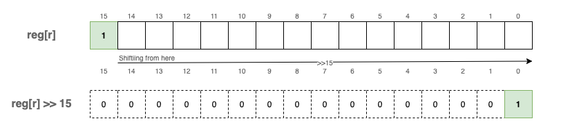
else if (reg[r] >> 15)
reg[RCND] = FN; // Result is negative (MSB is 1)
else
reg[RCND] = FP; // Result is positive
}
We call uf(r) after any instruction that modifies a register and affects condition codes.
A note on signed numbers: Even though we use uint16_t, our VM supports signed integers using Two’s Complement. By convention, if the most significant bit (position 15) is 1, the number is negative.
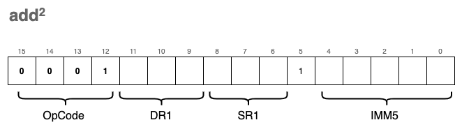
add - Adding two values
The ability to add numbers is fundamental to any CPU. In our VM, we define two variations of the add instruction. While they share the same OpCode, their encoding differs based on the value of bit[5], which determines how the second operand is interpreted.
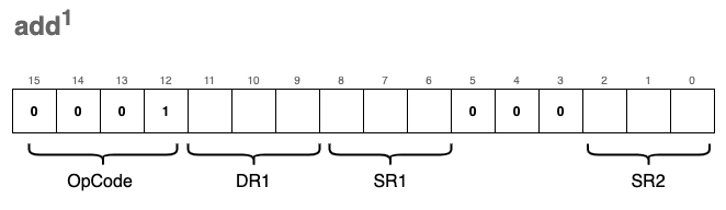
The first variation (register mode) adds the values of two source registers, SR1 and SR2, and stores the result in the destination register, DR1:
The second variation (immediate mode) adds a “constant” 5-bit value (IMM5) to SR1 and stores the result in DR1:

Note:
DRrefers to the Destination Register, whileSRrefers to the Source Register.
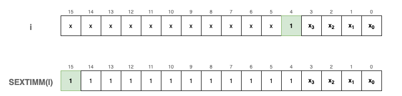
IMM5 is a 5-bit signed integer using Two’s Complement. Because the 5th bit acts as the sign bit, we must “extend” this sign to 16 bits so it can be mathematically added to our 16-bit registers.
We implement a sext (sign extend) function to handle this:
#define SEXTIMM(i) sext(IMM(i), 5)
static inline uint16_t sext(uint16_t n, int b) {
    // If the b-th bit of n is 1, the number is negative.
    // We fill the leading bits with 1s; otherwise, we leave it as is.
    return ((n >> (b - 1)) & 1) ? (n | (0xFFFF << b)) : n;
}
Visually, SEXTIMM(i) operates like this for negative numbers:
To verify this logic, consider an example where the 5-bit value is negative:
uint16_t a = 0x16; // Binary: 0000 0000 0001 0110 (The 5th bit is 1)
fprintf_binary(stdout, a);           // Output: 0000 0000 0001 0110
fprintf_binary(stdout, SEXTIMM(a));  // Output: 1111 1111 1111 0110
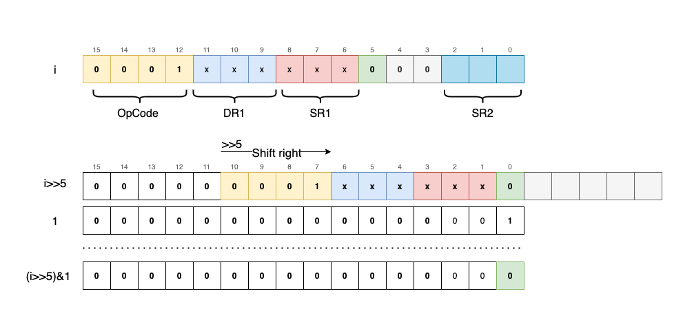
To differentiate between register mode and immediate mode, we extract the 5th bit using a bitwise mask:
// Shifts 'i' right by 5 bits to bring bit[5] to the last position, then masks with 1
#define FIMM(i) ((i >> 5) & 1)
We also use macros to extract register indices and the immediate value from specific bit ranges:
#define DR(i)  (((i) >> 9) & 0x7)  // Bits 11-9 (Destination Register)
#define SR1(i) (((i) >> 6) & 0x7)  // Bits 8-6  (Source Register 1)
#define SR2(i) ((i) & 0x7)         // Bits 2-0  (Source Register 2)
#define IMM(i) ((i) & 0x1F)        // Bits 4-0  (Immediate Value)
By combining these components, the add function checks the FIMM flag to decide whether to add a second register or a sign-extended immediate value. Finally, it updates the condition flags (uf) based on the result.
static inline void add(uint16_t i) {
    reg[DR(i)] = reg[SR1(i)] + (FIMM(i) ? SEXTIMM(i) : reg[SR2(i)]);

    // Update condition flags (Positive, Zero, or Negative)
    uf(DR(i));
}
and - Bitwise logical AND
This instruction is functionally very similar to add, and it likewise comes in two formats.
The first format (register mode) applies a bitwise AND (&) to the values of two registers, SR1 and SR2, storing the result in DR1:
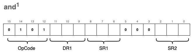
The second format (immediate mode) applies a bitwise AND between SR1 and a sign-extended IMM5 value, storing the result in DR1:
The same logic as before applies: we check bit[5] to determine which format to decode.
From a code perspective, the implementation is nearly identical to the add instruction and reuses the same macros. We simply swap the addition operator (+) for the bitwise AND operator (&):
static inline void and(uint16_t i)  {
    reg[DR(i)] = reg[SR1(i)] &
        (FIMM(i) ?                  // If the 5th bit is 1:
            SEXTIMM(i) :            // Sign-extend IMM5 and AND it with SR1
            reg[SR2(i)]);           // Otherwise, AND the value of SR2 with SR1
    uf(DR(i));  // Update the condition flags (Positive, Zero, or Negative)
}
ld - Load RPC + offset
The ld instruction loads data from a specific memory location into a destination register, DR. This memory location is calculated by adding a signed offset value to the current RPC (Program Counter) register. Importantly, calling ld does not modify the RPC itself; it simply uses the register as a reference point for the calculation.
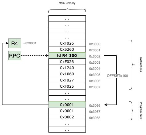
For example, if the RPC currently points to the memory address 0x3002 and our offset is set to 100, the VM will read the data from location 0x3002 + 100 = 0x3066 and load it into the specified destination register.
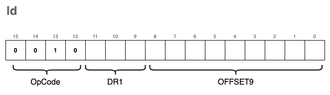
The instruction encoding looks like this:
The corresponding C implementation is:
#define POFF9(i) sext((i)&0x1FF, 9)

static inline void ld(uint16_t i) {
    // Calculate the target address using RPC + 9-bit signed offset
    reg[DR(i)] = mr(reg[RPC] + POFF9(i));
    // Update condition flags based on the loaded value
    uf(DR(i));
}
Because the offset is encoded in the last 9 bits of the instruction, it acts as a signed integer with a range from -256 to 255. This limits the “reach” of the instruction; it can only access memory locations within a small window relative to the RPC.
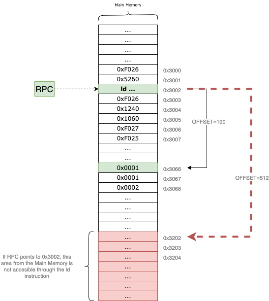
Specifically, $2^9 = 512$. Since the offset is signed, the maximum positive value it can represent is $511$ (in binary 0b111111111), assuming we don’t care about the sign bit, or $255$ if we treat it as two’s complement. This means that depending on where your program is located in memory, large sections of the address space may remain inaccessible to the ld instruction.
To overcome this addressability limitation, we need to introduce another instruction called ldi.
ldi - Load Indirect
The ldi (Load Indirect) instruction is used to load data into a register from a memory location that is “far away.” It bypasses the 9-bit offset limitation of the standard ld instruction by using an intermediary address as a pointer.
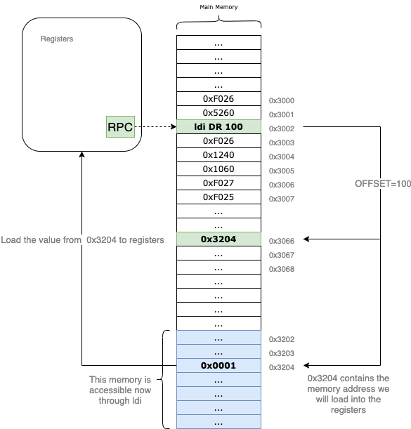
Let’s trace an example: suppose the RPC points to 0x3002. Just like with the ld instruction, we use a 9-bit signed offset to calculate a target address. If the offset = 100, the VM first looks at the memory address 0x3002 + 100 = 0x3066.
However, instead of loading the value 0x3066 into our destination register, the VM treats the content of 0x3066 as another address. If 0x3066 contains the value 0x3204, the VM performs a second read at 0x3204 and brings that data into the DR.
By using this “pointer” logic, ldi allows your program to access any location in the 16-bit address space, regardless of where the current RPC is.
Side-note: This doesn’t make
ldistrictly “better” thanld. Becauseldimust perform two memory reads to fetch one piece of data, it is computationally more expensive. It is a tool designed for a specific purpose: wide-range memory access.
The format of the instruction is nearly identical to ld, with only the OpCode changing to 0xA:
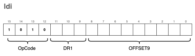
In C, we implement this double-lookup like this:
static inline void ldi(uint16_t i)  {
    // We perform two memory reads (mr):
    // 1. Calculate address from RPC + offset and read the pointer stored there.
    // 2. Read the final data from the pointer's address.
    reg[DR(i)] = mr(mr(reg[RPC] + POFF9(i)));

    // Update the condition flags
    uf(DR(i));
}
ldr - Load Base+Offset
This is yet another instruction used to load data from memory into registers. However, unlike ld which calculates the address relative to the RPC, ldr allows us to specify a custom base address—specifically, a memory address already stored in one of our general-purpose registers.
The encoding for this instruction is as follows:
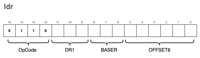
To extract the BASER (the register holding the base address) from the instruction, we can reuse the SR1(i) macro we defined earlier for ld, as the bits occupy the exact same positions (bits 8-6).
To extract the OFFSET6 ( a 6-bit signed offset), we use a new macro that isolates the last 6 bits and applies sign extension:
#define POFF(i) sext((i) & 0x3F, 6)
The C implementation is nearly identical to ld, with one crucial change: instead of referencing reg[RPC], we reference the base register specified in the instruction bits.
static inline void ldr(uint16_t i) {
    // Uses a general purpose register (SR1 bits) as the anchor
    reg[DR(i)] = mr(reg[SR1(i)] + POFF(i));
    uf(DR(i));
}
lea - Load Effective Address
The lea instruction is used to load raw memory addresses into registers. This is the key difference between it and instructions like ld, ldi, or ldr: while those fetch the content stored at an address, lea simply calculates the address itself and stores that value in the destination register.
The encoding format for lea is:
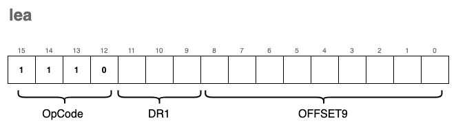
From a visual perspective, the instruction operates as a simple calculation relative to the Program Counter:
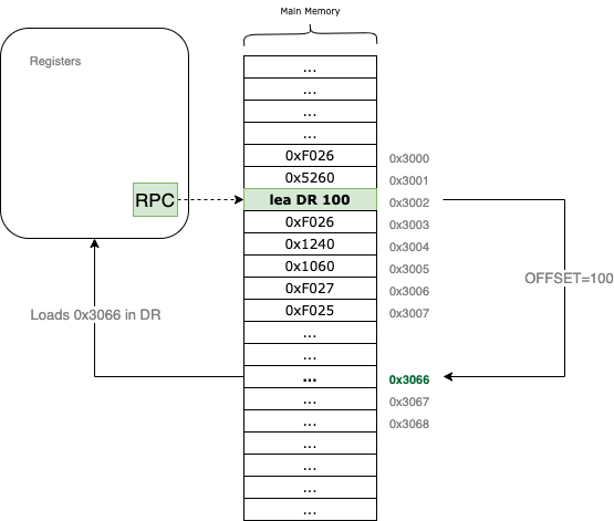
For example, if the RPC currently points to 0x3002 and the offset9 is set to 100, the VM will calculate 0x3002 + 100 = 0x3066. It then loads that address, 0x3066, directly into the specified DR register.
In C, the implementation is straightforward arithmetic followed by a condition flag update:
static inline void lea(uint16_t i) {
    // Calculate the address (RPC + 9-bit signed offset) and store it in DR
    reg[DR(i)] = reg[RPC] + POFF9(i);

    // Update the condition flags (N, Z, or P) based on the calculated address
    uf(DR(i));
}
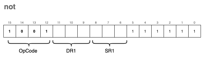
not - Bitwise Complement
The not instruction performs a bitwise complement (also known as a bitwise NOT) on the value stored in the source register SR1 and saves the result in the destination register DR.
The encoding format for the not instruction is:
In this operation, every 0 in the source bitmask is flipped to a 1, and every 1 is flipped to a 0. Since this operation modifies the contents of a register, we must also update the condition flags.
In C, the implementation uses the bitwise NOT operator (~):
static inline void not(uint16_t i) {
    // Perform bitwise NOT on SR1 and store the result in DR
    reg[DR(i)] = ~reg[SR1(i)];

    // Update the condition flags (N, Z, or P) based on the new value
    uf(DR(i));
}
st - Store
We use the st instruction to store the value of a given register back into a memory location. Think of this as the inverse of the ld instruction; instead of bringing data into the CPU, we are pushing it out to the Main Memory.
The encoding format for the instruction is:

Visually, this instruction works by calculating a target address relative to the Program Counter:
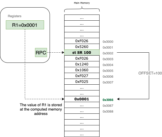
For example, if the RPC is pointing to 0x3002 and the source register SR (which uses the DR bit field in the encoding) refers to R1, which contains the value 0x0001. If the offset is 100, the st instruction will write the value 0x0001 directly to the memory address 0x3002 + 100 = 0x3066.
The C implementation is straightforward, using our mw (memory write) helper:
static inline void st(uint16_t i)  {
    // Write the value of the source register to the calculated memory address
    mw(reg[RPC] + POFF9(i), reg[DR(i)]);
}
Note that there is no need to update the condition flags (uf) here. Since we are only moving data to memory and not modifying the contents of any registers, the state of the flags remains unchanged.
Just like the ld instruction, st is limited by its 9-bit signed offset, meaning it can only store data to memory locations relatively close to the current RPC. To overcome this limitation, we use the sti instruction.
sti - Store Indirect
The encoding for sti (Store Indirect) is very similar to st, with only the OpCode changing to 0xB:
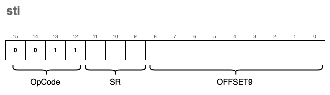
However, the behavior is significantly different. Much like ldi was the “pointer” version of a load, sti is the “pointer” version of a store.
Instead of writing data directly to the address calculated by RPC + offset, the VM treats the value stored at that address as a destination pointer. It reads that pointer first, and then writes the register’s data to the resulting memory location.
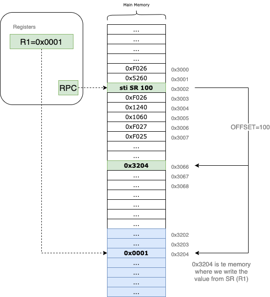
Let’s trace an example: suppose we want to write the content of R1 = 0x0001 to the address 0x3204, which is far beyond our 9-bit offset reach.
- The VM first calculates
RPC + offset(e.g.,0x3066). - It reads the value stored at
0x3066. If that value is0x3204, the VM now has its target. - Finally, it writes the value of
R1(0x0001) into the memory at0x3204.
In C, we implement this “double-hop” by nesting a memory read (mr) inside a memory write (mw):
static inline void sti(uint16_t i)  {
    // 1. Calculate RPC + offset.
    // 2. Read the address stored there (mr).
    // 3. Write the register value (DR bits) to that new address (mw).
    mw(mr(reg[RPC] + POFF9(i)), reg[DR(i)]);
}
This instruction is essential for modifying data in distant memory regions or handling global variables that aren’t located near the current instruction pointer.
str - Store Base + Offset
This instruction is the storing counterpart to ldr. It functions similarly to the standard st instruction, with one key difference: instead of calculating the destination address relative to the RPC, we use a Base Register (BASER) as our reference point.
The encoding format for the instruction is:
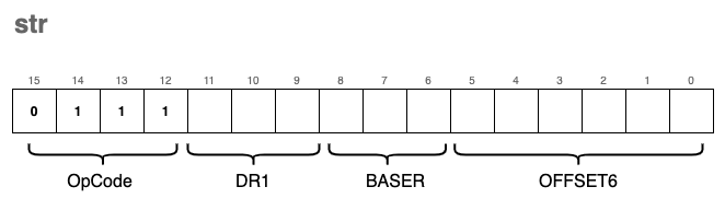
By using a base register, we can store data into memory locations relative to a pointer we’ve already calculated or loaded into a register (like R0 through R7). This is particularly useful for managing data structures, such as structs or arrays, where the base register points to the start of the structure and the OFFSET6 points to a specific field or element.
In C, the implementation reflects this shift in reference. We swap the RPC for the register index extracted from the SR1 bit field:
// Comparison: st vs str

static inline void st(uint16_t i)   {
    // Uses RPC as the anchor point for the store
    mw(reg[RPC] + POFF9(i), reg[DR(i)]);
}

// VERSUS

static inline void str(uint16_t i)  {
    // Uses a general-purpose register (BASER) as the anchor point
    // We reuse the SR1 macro to extract the base register index
    mw(reg[SR1(i)] + POFF(i), reg[DR(i)]);
}
Just like the other store instructions, str does not modify any registers and therefore does not require an update to the condition flags (uf).
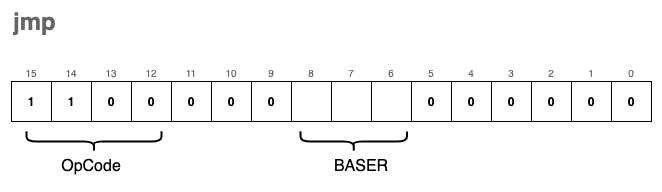
jmp - Jump
Under normal circumstances, the RPC (Program Counter) automatically increments after each instruction is executed, leading to a linear flow of execution. The jmp instruction breaks this sequence by forcing the RPC to “jump” to a new memory address.
The target address is not relative to the current position; instead, it is the exact value currently stored in a Base Register (BASER).
The encoding format for the instruction is:
Visually, the instruction works by overwriting the current Program Counter with the contents of the specified register:
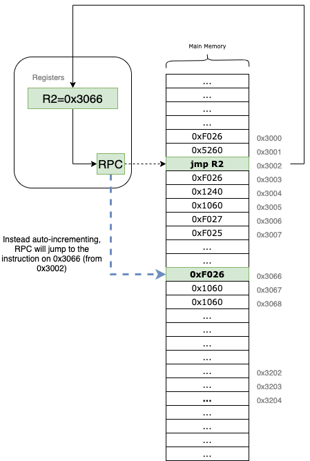
For example, if our RPC is at 0x3002 and the instruction specifies R2 as the BASER (which currently holds 0x3066), the VM will immediately set the RPC to 0x3066. The very next instruction to be fetched and executed will be the one located at that new address.
In high-level programming languages, jmp is the low-level equivalent of a goto statement. It is a powerful tool for creating loops, exiting subroutines, or navigating complex logic.
The corresponding C implementation is incredibly simple:
static inline void jmp(uint16_t i)  {
    // Set the Program Counter to the value held in the Base Register
    // We reuse our SR1 macro to extract bits 8-6 which define the BASER
    reg[RPC] = reg[SR1(i)];
}
Since jmp only modifies the RPC and does not perform any arithmetic on data registers, the condition flags (uf) are not updated.
jsr - Jump to Subroutine
The jsr (Jump to Subroutine) instruction is the foundation for implementing functions in our virtual machine. A subroutine is a reusable block of instructions that performs a specific task, often taking inputs from registers and returning a result in a register.
jsr is unique because it doesn’t just jump; it “remembers” where it came from so the program can eventually return to the next instruction after the function call.
The instruction comes in two distinct encoding formats:
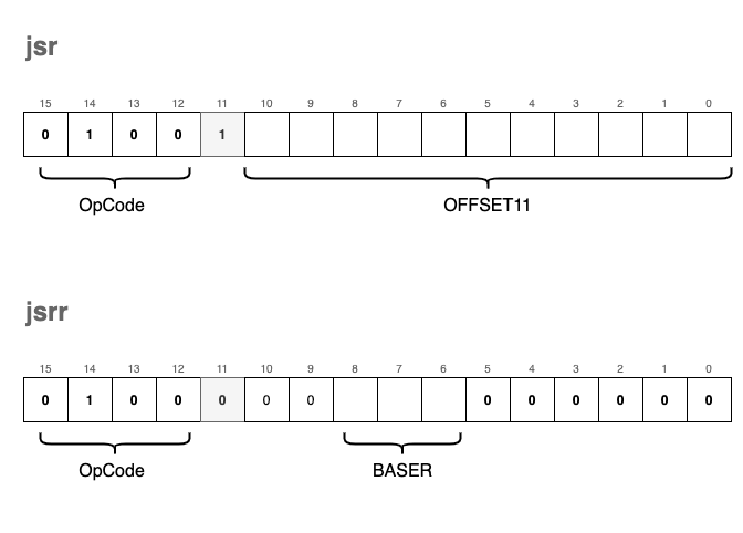
- Save Return Address: The current
RPCis saved into registerR7. This “links” the subroutine back to the calling code. - Determine Jump Type:
- If bit[11] is
1: It performs a PC-relative jump using an 11-bit signed offset (RPC = RPC + OFFSET11). - If bit[11] is
0: It performs a register-based jump (often calledjsrr), settingRPCto the value held in a specified Base Register.
- If bit[11] is
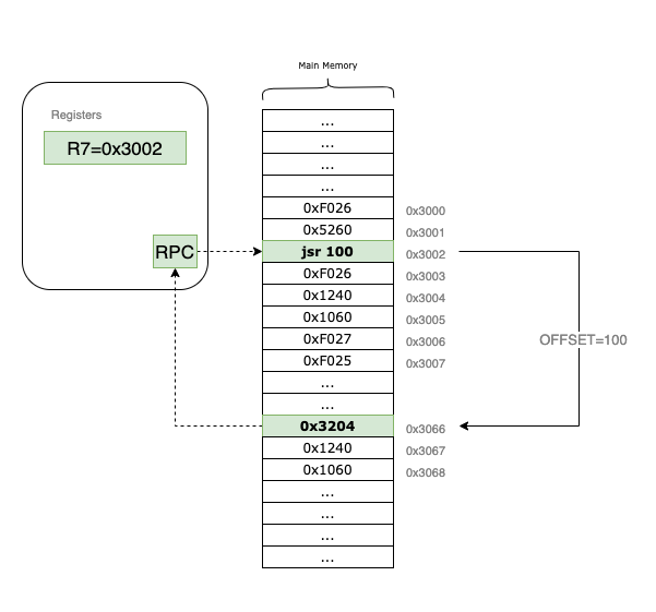
In the example above, the RPC starts at 0x3002. When the jsr instruction is executed, 0x3002 is tucked away in R7. The VM then applies the offset = 100, landing the RPC at 0x3066 to begin the subroutine. To return later, the programmer simply needs to jmp R7.
We use a macro FL(i) to check the state of bit 11 and POFF11(i) to extract and sign-extend the larger 11-bit offset.
#define FL(i) (((i) >> 11) & 1)
#define POFF11(i) sext((i) & 0x7FF, 11)

static inline void jsr(uint16_t i) {
    // First, save the current PC to R7 so we can return later
    reg[R7] = reg[RPC];

    // Then, update the PC based on bit 11
    reg[RPC] = (FL(i)) ?
        (reg[RPC] + POFF11(i)) :    // PC-relative mode
        (reg[SR1(i)]);              // Register mode (Base Register)
}
By storing the return address in R7, we enable our VM to handle complex logic across multiple subroutines, mimicking the behavior of high-level function calls.
br - Conditional Branch
The br instruction is the VM’s primary tool for decision-making. While it functions similarly to jsr by jumping to a new address, it has one major difference: the branch occurs only if specific conditions are met.
This is the low-level equivalent of an if statement.
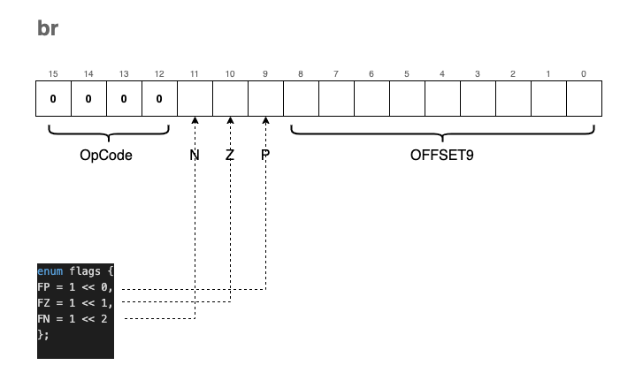
The encoding of the br instruction includes three “condition bits” labeled N, Z, and P:
- N: Negative
- Z: Zero
- P: Positive
These bits are not named by accident. They correspond exactly to the status flags we update in the RCND register whenever we call uf() (Update Flags) after an ALU operation:
enum flags { FP = 1 << 0, FZ = 1 << 1, FN = 1 << 2 };

static inline void uf(enum regist r) {
    if (reg[r] == 0)
        reg[RCND] = FZ;       // Result is Zero (010)
    else if (reg[r] >> 15)
        reg[RCND] = FN;       // Result is Negative (100)
    else
        reg[RCND] = FP;       // Result is Positive (001)
}
When the VM encounters a br instruction, it compares the condition bits provided in the instruction (NZP) against the current state of the RCND register. If there is a match (a bitwise “and” yields a non-zero result), the RPC is updated by adding the signed 9-bit offset.
For example, if the instruction has the Z bit set and the last operation resulted in a zero, the branch
trap
The trap instruction is arguably the most complex part of our VM because it serves as the bridge between our isolated virtual environment and the “outside world.” It allows our programs to interact with I/O devices—primarily the keyboard and the console.
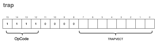
In a real LC-3 system, the TRAPVECT (the lower 8 bits of the instruction) acts as an index into a table of memory addresses where the actual service routines (written in ASM) reside. To keep our implementation concise, we are taking a shortcut: we map these trap vectors directly to native C functions.
If we were being strictly “kosher,” these routines would be loaded into the VM’s memory as LC-3 assembly. However, by using a separate array of function pointers, we can leverage the power of the C standard library for tasks like string printing and formatted input.
The Trap Dispatcher
We use a similar strategy for traps as we did for general instructions. We define an array trp_ex containing pointers to our handler functions:
#define TRP(i) ((i) & 0xFF) // Extract the 8-bit trap vector

static inline void tgetc();   // Function prototypes
static inline void tout();
// ... other trap prototypes ...

enum { trp_offset = 0x20 }; // Traps in LC-3 start at index 0x20
typedef void (*trp_ex_f)();

trp_ex_f trp_ex[8] = {
    tgetc, tout, tputs, tin, tputsp, thalt, tinu16, toutu16
};

static inline void trap(uint16_t i) {
    // Invoke the function corresponding to the trap vector minus the offset
    trp_ex[TRP(i) - trp_offset]();
}
Supported Trap Functions
Our VM supports 8 distinct trap routines:
| Trap Function | Vector | trp_ex Index | Description |
|---|---|---|---|
tgetc | 0x20 | 0 | Reads a character from the keyboard into R0. |
tout | 0x21 | 1 | Writes the character in R0 to the console. |
tputs | 0x22 | 2 | Writes a null-terminated string to the console, starting at the address in R0. |
tin | 0x23 | 3 | Reads a character into R0 and echoes it back to the console. |
tputsp | 0x24 | 4 | Not implemented. (Used for packed strings). |
thalt | 0x25 | 5 | Halts the program execution. |
tinu16 | 0x26 | 6 | Reads a 16-bit unsigned integer into R0. |
toutu16 | 0x27 | 7 | Prints the 16-bit unsigned integer in R0 to the console. |
Implementation Details
tgetc & tout
These handle single-character I/O. Note that for tout, we cast the register value to a char.
static inline void tgetc() { reg[R0] = getchar(); }
static inline void tout()  { fprintf(stdout, "%c", (char)reg[R0]); }
tputs
This function treats memory like a C-string. It starts at the address stored in R0 and keeps printing characters until it hits a 0x0000 (null terminator).
static inline void tputs() {
    uint16_t *p = mem + reg[R0];
    while(*p) {
        fprintf(stdout, "%c", (char)*p);
        p++;
    }
}
tin
Short for “Trap IN”, this is tgetc with an immediate echo to the screen so the user can see what they are typing.
static inline void tin() {
    reg[R0] = getchar();
    fprintf(stdout, "%c", (char)reg[R0]);
}
thalt
We use a global boolean variable running to control our main loop. Calling thalt simply flips this switch.
static inline void thalt() { running = false; }
tinu16 & toutu16
These are custom additions to our VM to make life easier. Instead of processing digits one by one in assembly, we use fscanf and fprintf to handle 16-bit integers directly.
static inline void tinu16() { fscanf(stdin, "%hu", ®[R0]); }
static inline void toutu16() { fprintf(stdout, "%hu\n", reg[R0]); }
Loading and Running Programs
Congratulations! If you have been coding along with this article, you now possess a functional “toy” Virtual Machine capable of executing programs written in our custom instruction set.
To finalize the project, we only need to implement two remaining components: the main execution loop and a mechanism to load binary programs into memory.
The Instruction Cycle (Main Loop)
The heart of the VM is the fetch-decode-execute cycle. Our start function initializes the Program Counter and enters a loop that continues until a HALT instruction is encountered.
bool running = true;
uint16_t PC_START = 0x3000;

void start(uint16_t offset) {
    // Initialize the RPC to the program start address
    reg[RPC] = PC_START + offset;

    while(running) {
        // FETCH: Read the instruction at the current RPC and increment it
        uint16_t i = mr(reg[RPC]++);

        // DECODE & EXECUTE: Extract the OpCode and call the mapped function
        op_ex[OPC(i)](i);
    }
}
Loading the Program Image
Next, we need a way to move our compiled binary files from the disk into the VM’s virtual RAM. The ld_img function opens a binary file and reads its contents directly into the mem array starting at our designated entry point.
void ld_img(char *fname, uint16_t offset) {
    // Open the program file in "read binary" mode
    FILE *in = fopen(fname, "rb");
    if (in == NULL) {
        fprintf(stderr, "Error: Could not open file %s.\n", fname);
        exit(EXIT_FAILURE);
    }

    // Set the pointer to the starting memory address (0x3000 + offset)
    uint16_t *p = mem + PC_START + offset;

    // Load the binary data into the memory array
    // We ensure we don't exceed the bounds of our virtual memory
    fread(p, sizeof(uint16_t), (UINT16_MAX - PC_START), in);

    fclose(in);
}
This method accepts:
fname: The path to the binary object file.offset: An optional adjustment to the starting memory address.
The Entry Point
Finally, we tie it all together in the main function. It takes the program path from the command line arguments, loads it, and starts the CPU.
int main(int argc, char **argv) {
    if (argc < 2) {
        fprintf(stderr, "Usage: %s <program.obj>\n", argv[0]);
        return EXIT_FAILURE;
    }

    // Load the image at the base address (no offset)
    ld_img(argv[1], 0x0);

    // Start execution
    start(0x0);

    return 0;
}
Our First Program
Our first program will not be the cliché “Hello, world!”, but something a bit more interactive: a piece of software that reads two numbers from the keyboard and elegantly prints their sum to stdout.
Jokes aside, here is what the raw machine code looks like:
0xF026    //  1111 0000 0010 0110  TRAP tinu16      ; read a uint16_t into R0
0x1220    //  0001 0010 0010 0000  ADD R1, R0, x0   ; copy R0 to R1 (R1 = R0 + 0)
0xF026    //  1111 0000 0010 0110  TRAP tinu16      ; read another uint16_t into R0
0x1240    //  0001 0010 0100 0000  ADD R1, R1, R0   ; R1 = R1 + R0
0x1060    //  0001 0000 0110 0000  ADD R0, R1, x0   ; copy result back to R0
0xF027    //  1111 0000 0010 0111  TRAP toutu16     ; print R0 to stdout
0xF025    //  1111 0000 0010 0101  HALT             ; stop the VM
The syntax isn’t exactly user-friendly, is it? Our program is actually just this series of hexadecimal numbers: 0xF026 0x1220 0xF026 0x1240 0x1060 0xF027 0xF025. However, if we look closer, we can see how the ASM instructions are encoded.
For example, let’s analyze 0xF026. Its binary representation is 1111 0000 0010 0110. It is easy to spot 1111 as the OpCode for trap, and the TRAPVECT of 0x26 correctly corresponds to our tinu16 function.
Or for a more visual breakdown, let’s look at the ADD instruction 0x1220:
0x1220 -> 0001   001   000   1   00000
          ADD    R1    R0    IMM  Value=0
Running Our First Program
Bad news: we don’t have a compiler or an assembler yet. We will have to write our programs by hand, using pen and paper (just like the pioneers of the old days).
The good news is that we don’t actually need a complex toolchain to generate a binary file that our VM can execute. We can simply write a small C “packer” for that.
The idea is to store our instructions in a uint16_t array and use fwrite() to generate a binary file, which we can then load using our ld_img() function.
#include <stdio.h>
#include <stdint.h>

uint16_t program[] = {
    0xF026,    // TRAP tinu16  (Read input to R0)
    0x1220,    // ADD R1,R0,x0 (Move R0 to R1)
    0xF026,    // TRAP tinu16  (Read second input to R0)
    0x1240,    // ADD R1,R1,R0 (R1 = R1 + R0)
    0x1060,    // ADD R0,R1,x0 (Move R1 to R0 for output)
    0xF027,    // TRAP toutu16 (Print R0)
    0xF025     // HALT         (Stop)
};

int main(void) {
    char *outf = "sum.obj";
    FILE *f = fopen(outf, "wb");
    if (!f) {
        fprintf(stderr, "Cannot open file %s for writing\n", outf);
        return 1;
    }

    // Write the instructions to the file
    size_t count = sizeof(program) / sizeof(uint16_t);
    fwrite(program, sizeof(uint16_t), count, f);

    printf("Successfully wrote %zu instructions to %s\n", count, outf);
    fclose(f);
    return 0;
}
If you compile and run this packer, it will generate a file named sum.obj. You can then use your VM to load and execute it:
The repository also includes simple_program.c, which demonstrates a loop summing up the elements of an array. It is highly recommended to check it out to see how the condition flags (br) work in a real scenario.
Final Thoughts
Thank you for reading this far! If you followed along, you now have a functioning Virtual Machine on your machine.
Writing a simple “toy” like this is a great exercise, but building something production-ready is significantly more complex, involving memory protection, advanced I/O, and much more.
Perhaps in a future article, we will explore a Stack-Based VM or a modern register-stack hybrid.
After sharing this article with various communities (the feedback was fantastic!), some suggested that the naming conventions were a bit terse or non-standard. While I wouldn’t typically name functions this way in a large-scale project, it felt natural for a low-level project where ASM naming conventions are inherently brief. This code was designed to be a concise companion to the explanations provided here.
Community Links
Source Code & Contributions
Spot an error or have an improvement? Open a PR directly for this article .